- Welcome to OI Roundtable.
Recent posts
#51
Electrical and Electronic / Re: What is a Low peak Fuse?
Last post by brianc75 - March 29, 2024, 07:12:AMI agree, I think Low-Peak fuses are just the name assigned to this style, it's not actually a fuse type.
#52
Electrical and Electronic / Re: What does Watt Loss mean?
Last post by brianc75 - March 29, 2024, 07:11:AMWatt loss is imminent for every device due to the sum of all components combined.
#53
Electrical and Electronic / Re: Simple Frequency Drive Dia...
Last post by brianc75 - March 29, 2024, 07:09:AMThe basic frequency drive diagram reminds me of an electrical one-line diagram.
#54
Troubleshooting 101 / Re: ABB ACS160 Alarm Codes and...
Last post by benklassne - February 22, 2024, 03:56:AMGreat job with the code lists for the 160 drive! These posts are helpful for quick alarm reference.


#55
The Maintenance Saloon / Re: Power Tech Drive Reviews
Last post by benklassne - February 18, 2024, 07:14:AMWhere are Power Tech drives made? This is where I would start this conversation. Country of manufacture matters when I buy any drive for any application. Power Tech isn't a very popular brand.
#56
Electrical and Electronic / Re: Cutler Hammer Contactor Ti...
Last post by benklassne - February 18, 2024, 07:11:AMI actually had some recent experience with Cutler hammer contactors. I purchased an aftermarket Cutler Hammer contact kit that is coated with a silver alloy. I double checked the size and the load on the contactor and everything checks out within spec. All I can do is wait it out and see how it holds up. They were made in Mexico. It would be hard to tell at this point if these contacts are any good.
#57
Troubleshooting 101 / Re: ABB ACS140 Fault, Alarm, a...
Last post by benklassne - February 18, 2024, 07:06:AMAgain, nice job with these code lists for the 140 drive!


#58
Troubleshooting 101 / Re: ABB ACS100 Fault Alarm and...
Last post by benklassne - February 18, 2024, 07:02:AMAgain, nice job with these code lists!


#59
Troubleshooting 101 / ABB ACS160 Alarm Codes and Fau...
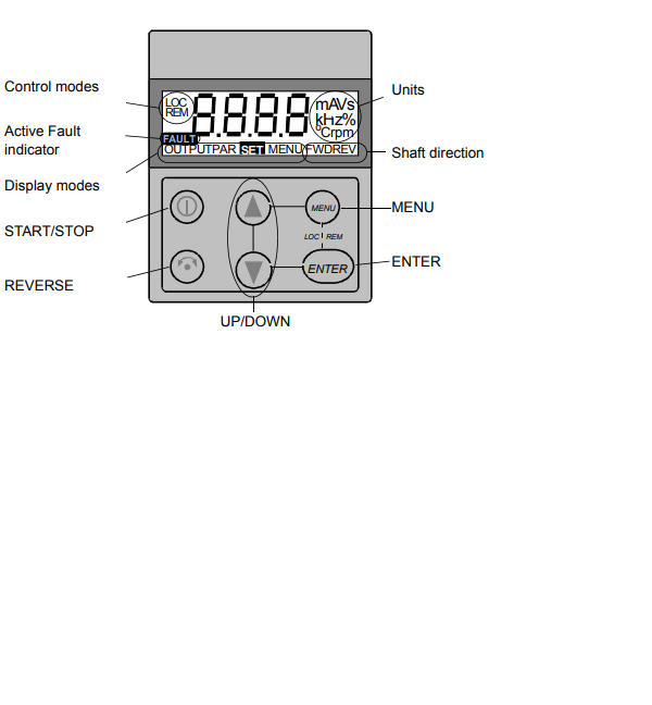
Last post by zigmund - February 18, 2024, 04:58:AMThe ABB ACS160 is a reliable drive but even reliable drives are prone to faults and occasional alarms. The seven-segment display of the control panel indicates alarms and faults using codes "ALxx"
or "FLxx", where xx is the corresponding alarm or fault code. Errors are part of life with any brand and ABB keeps the display simple.
As a couple quick notes, the alarm and fault messages disappear when MENU, ENTER or the arrow buttons of control panel are pressed. The message will reappear after a few seconds if the keypad is not touched and the alarm or fault is still active.
Also the last three fault codes are stored into parameters 0128 to 0130. These faults can be cleared from the control panel by pressing UP and DOWN buttons at the same time in parameter set mode or through serial communication mode by writing 0 into them.
The faults can be reset either from the control panel (by pressing START/STOP button), by digital input (Parameter 1604) or serial communication, or switching the supply voltage off for a while. When the fault has been removed, the motor can be started. The ACS160 can be configured to automatically reset certain faults. This would be done in parameter group 31.
AUTOMATIC RESET. OK Here is the list of codes:
LIST OF ACS160 ALARMS
Pay attention to Notes!
Alarms (*) will not cause relay output RO1 (RO2) to activate when the relay output is configured to indicate alarm condition in general. (Parameter 1401 RELAY OUTPUT 1 (1402 RELAY OUTPUT 2) has value 5 (ALARM) or 13 (FLT/ALARM)).
Note! Alarms (**) will be shown only if parameter 1608 DISPLAY ALARMS is set to 1 (YES)
LIST OF ACS160 FAULTS
or "FLxx", where xx is the corresponding alarm or fault code. Errors are part of life with any brand and ABB keeps the display simple.
As a couple quick notes, the alarm and fault messages disappear when MENU, ENTER or the arrow buttons of control panel are pressed. The message will reappear after a few seconds if the keypad is not touched and the alarm or fault is still active.
Also the last three fault codes are stored into parameters 0128 to 0130. These faults can be cleared from the control panel by pressing UP and DOWN buttons at the same time in parameter set mode or through serial communication mode by writing 0 into them.
The faults can be reset either from the control panel (by pressing START/STOP button), by digital input (Parameter 1604) or serial communication, or switching the supply voltage off for a while. When the fault has been removed, the motor can be started. The ACS160 can be configured to automatically reset certain faults. This would be done in parameter group 31.
AUTOMATIC RESET. OK Here is the list of codes:
LIST OF ACS160 ALARMS
- 1 * OPERATION FAILED Parameter upload or download failed. The software versions of the drives may not be compatible. Software version can be seen from parameter 3301 SOFTWARE VERSION.
- 2 * START ACTIVE Control panel function is not allowed while start is active.
- 3 * LOCAL/REMOTE Control panel function is not allowed in current control mode (local or remote). Control mode is local when LOC is displayed and remote mode when REM is displayed on the control panel.
- 5 * BUTTON DISABLED Control panel function is denied for any of the following reasons: • START/STOP button is interlocked from digital input. This can happen with certain digital input configurations. Refer to section on Application Macros. • REVERSE button is locked because shaft direction is fixed by parameter 1003 DIRECTION. • The drive is in remote control mode and START/STOP and REVERSE buttons are not followed.
- 6 * PARAM/LOCAL LOCK Control panel function is not allowed: • Parameter 1602 PARAMETER LOCK denies parameter editing • Parameter 1605 LOCAL LOCK denies local control mode.
- 7 * FACTORY MACRO Control panel function is not allowed: Factory macro is selected and denies the parameter modifications. Factory macro is intended for applications where there is no control panel available.
- 10 ** OVERCURRENT Overcurrent controller is active.
- 11 ** OVERVOLTAGE Overvoltage controller is active.
- 12 ** DC UNDERVOLTAGE Undervoltage controller is active.
- 13 DIRECTION LOCK Rotation direction if fixed by parameter 1003 DIRECTION.
- 14 SERIAL COMM LOSS Serial communication through Standard Modbus Channel is lost. • Check connections between external control system and the ACS160. • Refer to parameters 5204 COMM FAULT TIME and 5205 COMM FAULT FUNC.
- 15 *, ** MODBUS EXCEPTION Exception response is sent through Standard Modbus channel. The bus master may be sending queries which cannot be processed by the ACS160. Last three exception response codes are stored into parameters 5213 - 5215.
- 16 AI1 LOSS Analogue input 1 loss. Analogue input 1 value is less than MINIMUM AI1 (1301). See also parameter 3001 AI<MIN FUNCTION.
- 17 AI2 LOSS Analogue input 2 loss. Analogue input 2 value is less than MINIMUM AI2 (1306). See also parameter 3001 AI<MIN FUNCTION.
- 18 PANEL LOSS Panel communication loss. Control panel is disconnected when - Drive is in local control mode (LOC is shown in the control panel display), or - Drive is in remote control mode (REM) and is parameterized to accept start/stop, direction or reference from the panel. Refer to parameters in groups 10 COMMAND INPUTS and 11 REFERENCE SELECT. See also parameter 3002 PANEL LOSS.
- 19 ** ACS160 OVERTEMP ACS 160 overtemperature condition. This alarm is given when the temperature reaches 95% of the trip limit.
- 20 MOTOR OVERTEMP Motor overtemperature condition as estimated by the ACS 160. Refer to parameters 3004 – 3008.
- 21 UNDERLOAD Motor load is too low. Check for a problem in the driven equipment. Refer to parameters 3013 – 3015.
- 22 MOTOR STALL Motor is operating in the stall region. This may be caused by excessive load or insufficient motor power. Refer to parameters 3009 – 3012.
- 23 Reserved.
- 24 Reserved.
- 25 Reserved.
- 26 ** OUTPUT OVERLOAD Inverter overload condition. The ACS 160 output current exceeds the ratings given in Reference Section P.
- 27 * AUTOMATIC RESET ACS 160 is about to perform automatic fault reset operation. As a result, the drive may start after the reset operation. Refer to parameter group 31 AUTOMATIC RESET.
- 28 * PID SLEEP PID sleep function is active. The drive may accelerate when PID sleep function is deactivated. Refer to parameters 4018 SLEEP SELECTION, 4013 PID SLEEP DELAY, 4014 PID SLEEP LEVEL nd 4015 WAKE-UP LEVEL.
- 29 Reserved.
- 30 Reserved.
- 31 BR RES OVERLOAD Brake resistor is nearly overloaded. Refer to brake resistor instructions.
Pay attention to Notes!
Alarms (*) will not cause relay output RO1 (RO2) to activate when the relay output is configured to indicate alarm condition in general. (Parameter 1401 RELAY OUTPUT 1 (1402 RELAY OUTPUT 2) has value 5 (ALARM) or 13 (FLT/ALARM)).
Note! Alarms (**) will be shown only if parameter 1608 DISPLAY ALARMS is set to 1 (YES)
LIST OF ACS160 FAULTS
- OVERCURRENT Output current is excessive. • Motor load may be too high • Acceleration time may be too short (parameters 2201 ACCELER TIME 1 and 2203 ACCELER TIME 2). • Motor or motor cable is faulty or connected wrong.
- 2 DC OVERVOLTAGE Intermediate circuit DC voltage is excessive. • Check mains for static or transient overvoltages • Deceleration time may be too short (parameters 2202 DECELER TIME 1 and 2204 DECELER TIME 2) • Brake chopper (if present) may be underdimensioned
- 3 ACS160 OVERTEMP ACS160 heat sink temperature is excessive. Temperature trip limit is 105 degree C. • Check air flow and fan operation. • Check motor power against unit power.
- 4 ** SHORT CIRCUIT Fault current. Possible reasons for this fault are: • There is a short-circuit in the motor cable(s) or motor • Supply disturbances
- 5 OUTPUT OVERLOAD Inverter overload condition. The ACS 160 output current exceeds the ratings given in Reference Section P.
- 6 DC UNDERVOLTAGE Intermediate circuit DC voltage is not sufficient. • Mains phase may be missing • Fuse may be blown
- 7 ANALOGUE INPUT 1 Analogue input 1 loss. Analogue input value is less than MINIMUM AI1 (1301). See also parameter 3001 AI<MIN FUNCTION.
- 8 ANALOGUE INPUT 2 Analogue input 2 loss. Analogue input value is less than MINIMUM AI2 (1306). See also parameter 3001 AI<MIN FUNCTION.
- 9 MOTOR OVERTEMP Motor overtemperature condition as estimated by the ACS 160. Refer to parameters 3004 – 3008.
- 10 PANEL LOSS Panel communication loss. Control panel is disconnected when the drive is receiving start, stop and direction commands from the panel. - Drive is in local control mode (LOC is shown in the control panel display), or - Drive is in remote control mode (REM is shown) and is parameterised to accept start/stop, direction or reference from the panel. Refer to parameters in groups 10 COMMAND INPUTS and 11 REFERENCE SELECT. See also parameter 3002 PANEL LOSS.
- 11 PARAMETERING Parameter values are inconsistent: • MINIMUM AI1 > MAXIMUM AI1 (parameters 1301, 1302) • MINIMUM AI2 > MAXIMUM AI2 (parameters 1304, 1305) • MINIMUM FREQ > MAXIMUM FREQ (parameters 2007, 2008)
- 12 MOTOR STALL Motor stall. This may be caused by excessive load or insufficient motor power. Refer to parameters 3009 – 3012.
- 13 SERIAL COMM LOSS Serial communication through Standard Modbus Channel is lost. • Check connections between external control system and the ACS160. • Refer to parameters 5204 COMM FAULT TIME and 5205 COMM FAULT FUNC.
- 14 EXTERNAL FAULT SIGNAL External fault is active. See parameter 3003 EXTERNAL FAULT.
- 15 ** OUTPUT EARTH FAULT Earth fault. The load on the incoming mains system is out of balance. • There may be a fault in the motor or motor cable. • Motor cable may be too long.
- 16 ** DC BUS RIPPLE • Ripple voltages on the DC bus are too large. • Mains phase may be missing • Fuse may be blown
- 17 UNDERLOAD Motor load is too low. Check for a problem in the driven equipment. Refer to parameters 3013 – 3015.
- 18 Reserved
- 19 Reserved.
- 20 ** AI OUT OF RANGE Analogue input out of range. Check AI level.
- 21 - 29 ** HARDWARE ERROR Hardware error. Contact supplier.
- 30 BR RES OVERLOAD Brake resistor is overloaded. Refer to parameter 2005 OVERVOLT CTRL.
- 31 ENCODER FAULT Positioning macro is used, but the drive is not receiving pulses. Check the encoder and its connections. Full display blinking Serial link failure. Bad connection between the control panel and the
ACS 160.
Pay attention to Note! Faults (**) are indicated by a red blinking LED and are reset by turning the power off for a while.
Also there is plenty of other info for clearing ACS160 faults in the user manual if you have access to one.
#60
Troubleshooting 101 / ABB ACS140 Fault, Alarm, and E...
Last post by zigmund - February 10, 2024, 07:31:AMABB ACS140 Fault, Alarm, and Error Codes
Alarm and Fault Displays
Here is some good general info from their service manual. The seven-segment display unit of control panel indicates alarms and faults using codes "ALxx" or "FLxx", where xx is the corresponding alarm or fault code. Alarms 1-7 arise from button operation. Green LED blinks for AL10-21, meaning that the ACS140 cannot fully follow the control commands. The faults are indicated by red LED. The alarm and fault messages disappear by pressing MENU, ENTER or the arrow buttons of the control panel. The message will reappear after a few seconds if the keypad is not touched and the alarm or fault is still active. Last three fault codes are stored into parameters 0128-0130. These fault memories can be cleared from the control panel by pressing UP and DOWN buttons simultaneously in parameter set mode.

Fault Resetting
When the red LED of the ACS140 is on or blinking, a fault is active!!!
When the green LED of the ACS140 is blinking, an alarm is active!!!
Resetting or clearing a fault is half the battle, the other hand is clearing the error and removing the problem all together. Faults that are indicated by a red blinking LED are reset by turning the power off for a while. Other faults (indicated by red static LED) can be reset either from the control panel, by digital input or serial communication, or switching the supply voltage off for a while. When the fault has been removed, the motor can be started. The ACS140 can be configured to automatically reset certain faults. Refer to parameter group 31 AUTOMATIC RESET.
It is important to remember that if an external source for start command is selected and is still active, the ACS140 may start immediately after a fault reset.
ALARM CODE LIST
Note! The Alarms marked with an asterisk (*) will be shown only if parameter 1608 DISPLAY ALARMS is set to 1(YES) so you may not see them depending on your setting
-------------------
FAULT CODE LIST
Note! Faults marked with an asterisk (*) are indicated by a red blinking LED are reset by turning the power off and on. Other faults are reset by pressing the START/STOP button. See also parameter 1604.
I'm sure this will be a big help for anyone troubleshooting the ACS140, Good Luck!
Alarm and Fault Displays
Here is some good general info from their service manual. The seven-segment display unit of control panel indicates alarms and faults using codes "ALxx" or "FLxx", where xx is the corresponding alarm or fault code. Alarms 1-7 arise from button operation. Green LED blinks for AL10-21, meaning that the ACS140 cannot fully follow the control commands. The faults are indicated by red LED. The alarm and fault messages disappear by pressing MENU, ENTER or the arrow buttons of the control panel. The message will reappear after a few seconds if the keypad is not touched and the alarm or fault is still active. Last three fault codes are stored into parameters 0128-0130. These fault memories can be cleared from the control panel by pressing UP and DOWN buttons simultaneously in parameter set mode.

Fault Resetting
When the red LED of the ACS140 is on or blinking, a fault is active!!!
When the green LED of the ACS140 is blinking, an alarm is active!!!
Resetting or clearing a fault is half the battle, the other hand is clearing the error and removing the problem all together. Faults that are indicated by a red blinking LED are reset by turning the power off for a while. Other faults (indicated by red static LED) can be reset either from the control panel, by digital input or serial communication, or switching the supply voltage off for a while. When the fault has been removed, the motor can be started. The ACS140 can be configured to automatically reset certain faults. Refer to parameter group 31 AUTOMATIC RESET.
It is important to remember that if an external source for start command is selected and is still active, the ACS140 may start immediately after a fault reset.
ALARM CODE LIST
- AL 1 Parameter upload/download failed.
- AL 2 Operation not allowed while start is active.
- AL 3 Operation not allowed in current control mode (Local or Remote).
- AL 5 Start/Stop/Direction or reference from control panel is not followed. Possible causes: ï Remote mode: parameters disable the buttons (See APPENDIX.) ï Local mode: START/STOP button interlocked from digital inputs.
- AL 6 Operation not allowed. Parameter 1602 PARAMETER LOCK is active.
- AL 7 Use of factory macro disables operation.
- AL10* Overcurrent controller active.
- AL11* Overvoltage controller active.
- AL12* Undervoltage controller active.
- AL13 Direction lock. See parameter 1003 DIRECTION.
- AL14 Serial communication loss alarm, see ACS140 RS485 and RS232 Adapter Installation and Start-up Guide.
- AL15* Modbus exception response is sent through serial communication.
- AL16 Analogue input 1 loss. Analogue input 1 value is less than MINIMUM AI1 (1301). See also parameters 3001 AI<MIN FUNCTION and 3013 AI1 FAULT LIMIT.
- AL17 Analogue input 2 loss. Analogue input 2 value is less than MINIMUM AI2 (1306). See also parameters 3001 AI<MIN FUNCTION and 3014 AI2 FAULT LIMIT.
- AL18* Panel loss. Panel is disconnected when Start/Stop/Dir or reference is coming from panel. See parameter 3002 PANEL LOSS and APPENDIX of manual.
- AL19* Hardware overtemperature (at 95 % of the trip limit).
- AL20* Motor overtemperature (at 95 % of the trip limit), see 3004 MOTOR THERM PROT.
- AL21 Motor stall alarm. See parameter 3009 STALL FUNCTION.
Note! The Alarms marked with an asterisk (*) will be shown only if parameter 1608 DISPLAY ALARMS is set to 1(YES) so you may not see them depending on your setting
-------------------
FAULT CODE LIST
- FL 1 Overcurrent: ï Possible mechanical problem. Check for: Acceleration and/or deceleration times may be too short. OR Supply disturbances.
- FL 2 DC overvoltage: Check for: Input voltage too high. OR Deceleration time may be too short.
- FL 3 ACS140 overtemperature: Check for Ambient temperature too high. OR Severe overload.
- FL 4 * Fault current: Check for: Output earth fault (200 V units). OR Short circuit. OR Supply disturbances.
- FL 5 Output overload.
- FL 6 DC undervoltage.
- FL 7 Analogue input 1 fault. Analogue input 1 value is less than MINIMUM AI1 (1301). See also parameters 3001 AI<MIN FUNCTION and 3013 AI1 FAULT LIMIT.
- FL 8 Analogue input 2 fault. Analogue input 2 value is less than MINIMUM AI2 (1304). See also parameters 3001 AI<MIN FUNCTION and 3014 AI2 FAULT LIMIT.
- FL 9 Motor overtemperature. See parameters 3004-3008.
- FL10 Panel loss. Panel is disconnected when Start/Stop/Dir or reference is coming from panel. See parameter 3002 PANEL LOSS and APPENDIX in manual. Note! If FL10 is active when the power is turned off, the ACS140 will start in remote control (REM) when the power is turned back on.
- FL11 Parameters inconsistent. Possible fault situations: Check for MINIMUM AI1 > MAXIMUM AI1 (parameters 1301 and 1302) OR MINIMUM AI2 > MAXIMUM AI2 (parameters 1304 and 1305) OR MINIMUM FREQ > MAXIMUM FREQ (parameters 2007 and 2008)
- FL12 Motor stall. See parameter 3009 STALL FUNCTION.
- FL13 Serial communication loss.
- FL14 External fault is active. See parameter 3003 EXTERNAL FAULT.
- FL15 Output earth fault (400 V units).
- FL16 * DC bus ripple too large. Check supply.
- FL17 Analogue input out of range. Check AI level.
- FL18 - FL22 * Hardware error. Contact supplier.
- Full display blinking Serial link failure. Bad connection between the control panel and the ACS140. Check if the Serial communication parameters (group 52) have been altered. Keep panel connected and switch power off and then on again.
Note! Faults marked with an asterisk (*) are indicated by a red blinking LED are reset by turning the power off and on. Other faults are reset by pressing the START/STOP button. See also parameter 1604.
I'm sure this will be a big help for anyone troubleshooting the ACS140, Good Luck!
