News:

Obsolete industrial electronics forum is still alive and well, just undergoing some maintenance and more anti spam stuff, stand by for a better experience

Main Menu

Menu

Show posts

This section allows you to view all posts made by this member. Note that you can only see posts made in areas you currently have access to.

Show posts Menu

Messages - drives-technician

#1
And here's the ABB DCS Alarm List:


  • A101 - Coast Stop (Off2) via Digital Input
    The Coast Stop (Off2) digital input is cleared.

  • A102 - Emergency Stop (Off3) via Digital Input
    The Emergency Stop (Off3) digital input is cleared.

  • A103 - DC Breaker Acknowledge Missing (Selected Motor)
    The DC Breaker Acknowledge digital input is cleared.

  • A104 - Converter Overtemperature
    The drive internal temperature is within 5°C of the temperature limit.

  • A105 - Dynamic Braking in progress
    For non-US dynamic braking, the DynBrakeAck input is set while in the ON state

  • A106 - Motor 1 Overtemperature
    The motor 1 temperature exceeds the temperature limit.

  • A107 - Motor 1 Overload
    The motor 1 current exceeds the overload limit.

  • A109 - Motor 2 Overtemperature
    The motor 2 temperature exceeds the temperature limit.

  • A110 - Motor 2 Overload
    The motor 2 current exceeds the overload limit.

  • A111 - Mains Low Voltage
    The mains voltage is below the alarm limit.

  • A112 - Peer to Peer, Master-Follower Communication Loss
    DCS-Link or fieldbus communications have been interrupted for a period longer than the limit.

  • A113 - SDCS-COM-8 Communication Loss
    Overriding control and/or master-follower communications through channel 0 or 2 of the COM-8
    have been interrupted for a period longer than the limit

  • A114 - Armature Current Deviation
    Current reference differs from current actual by more than a limit for longer than a time limit. See alarm description in DCS800 Firmware Manual for what to check in the event of a fault.

  • A115 - Tachometer Range (Selected Motor)
    If this alarm is present for longer than 10 seconds, the signal from the tachometer analog input exceeded a limit. If present for 10 seconds and then it clears, it is an indication that M1OvrSpeed (30.16) or M2OvrSpeed (49.21) has changed and a new tach fine tuning is required.

  • A116 - Mechanical Brake (Selected Motor)
    Active only when BrakeFaultFunc (42.06) = CRANE, the acknowledge signal for brake engaged is missing for a period longer than the engage limit.

  • A117 - Armature Current Ripple
    DC current ripple exceeds the limit. If this occurs during start up, then current controller gain may be set too high. Otherwise, this is often an indication that one or more thyristors is not working or a fuse is blown.

  • A118 - Found New Application on Memory Card
    An application has been found on SDCS-MEM8 used with ControlBuilder.

  • A119 - Application Mismatch between Drive and Memory Card
    The applications previously loaded to the drive and the one on the SDCS-MEM8 do not match.

  • A120 - Overvoltage Protection Active
    The overvoltage protection unit, DCF506-xxxx-51 is active, so the controller is blocking the converter output.

  • A121 - Autotuning Failed
    Autotuning has failed.

  • A122 - Mechanical Brake (Selected Motor)
    Active only when BrakeFaultFunc (42.06) ? FAULT, the acknowledge signal for brake open or brake engaged is missing for a period longer than the open or engage limit. Or torque actual does not reach the torque limit, used, for example, for cranes with a hanging load.

  • A124 - Speed Scaling Out of Range
    See: Motor 1: 50.01, 20.01, 20.02, 99.04 and Motor 2: 49.22, 49.03, 49.19, 49.20

  • A125 - Speed Feedback (Selected Motor)
    Speed feedback from a tachometer or encoder is continuously compared to EMF feedback while running. A fault indicates that the EMF voltage was above a voltage limit (30.15) while the motor speed was below a speed limit (30.14). This usually indicates there is a problem with the tachometer or encoder.

  • A126 - External Alarm via Digital Input
    The External Alarm digital input is set.

  • A127 - Analog Input Out of Range
    One of the analog input values is below the minimum limit.

  • A128 - Fieldbus Communications Loss
    Fieldbus Communications have been interrupted for a period longer than a time limit after the first data set from the overriding control has been received.

  • A129 - Parameters Restored
    The parameters found in flash were invalid at power-up (checksum fault). All parameters were restored from the parameter backup.

  • A130 - Local Command Loss
    Communications have been interrupted with the control panel, Drive Window, or Drive Window Light while in Local Control Mode

  • A131 - Parameter Added
    A new firmware program with a different amount of parameters was downloaded. The new parameters are set to their default value.

  • A132 - Parameter Setting Conflict
    The settings of some parameters are in conflict with each other.

  • A133 - Retained Data Invalid
    The retained data was invalid at power-up; the backup data was used. Backup data reflects the status during the previous power-up. Retained data includes: fault logger data, Data1 (19.01) thru Data4 (19.04), I/O options (see group 98), parameters defined by means of DCS800 ControlBuilder when the RETAIN box is checked.

  • A134 - Parameter Compatibility
    When downloading parameter sets or during powerup the firmware attempts to write the parameters. If setting of a parameter is not possible or not compatible, the parameter is set to default.

  • A135 - Parameter Upload or download Failed
    The checksum verification failed following a parameter upload or download. Please try again

  • A136 - Adaptive Program Task Time Not Set
    The task time for Adaptive Programming is not set when the user attempted to start it.

  • A137 - Speed Not Zero
    Drive was restarted before the motor decelerated below the zero speed limit.

  • A138 - Off2 (Coast Stop) Fieldbus
    Bit 1 from the main control word is not set, causing a start inhibit condition.

  • A139 - Off3 (Emergency Stop) Fieldbus
    Bit 2 from the main control word is not set, causing an estop condition.

  • A140 - Illegal Fieldbus Settings
    The fieldbus parameters in group 51 (fieldbus) are not set according to the fieldbus adapter or the device has not been selected.

  • A141 - SDCS-COM8 Firmware Version Conflict
    Invalid combination of drive (SDCS-CON-4) firmware and SDCS-COM-8 firmware. Drive firmware 3.7 is compatible with SDCS-COM-8 firmware 1.80 or higher. See firmware release notes for complete compatibility list. Typically requires upgrading to a newer SDCSCOM-8 board

  • A142 - Memory Card Missing
    A ControlBuilder application has been loaded in the drive but the memory card belonging to that application has not been found.

  • A143 - Memory Card Failure
    The data found in the memory card was invalid (checksum fault).

#2
Here's a general list of ABB faults and alarms for the DCS drive manual, they should pertain to all these models:

DCS800-EP1-0020-05, DCS800-EP2-0025-05, DCS800-EP1-0045-05, DCS800-EP2-0050-05, DCS800-EP1-0065-05, DCS800-EP2-0075-05, DCS800-EP1-0090-05, DCS800-EP2-0100-05, DCS800-EP1-0125-05, DCS800-EP2-0140-05, DCS800-EP1-0180-05, DCS800-EP2-0200-05, DCS800-EP1-0230-05, DCS800-EP2-0260-05, DCS800-EP1-0315-05, DCS800-EP2-0350-05,  DCS800-EP1-0405-05, DCS800-EP2-0450-05, DCS800-EP1-0470-05, DCS800-EP2-0520-05, DCS800-EP1-0610-05, DCS800-EP2-0680-05, DCS800-EP1-0740-05, DCS800-EP2-0820-05,
DCS800-EP1-0900-05, DCS800-EP2-1000-05, DCS800-EP2-1010-05

Here's the ABB DCS Fault List:


  • F501 - Auxiliary Undervoltage Limit
    The auxiliary voltage is too low at terminal X99 on PIN-4 or POW-4 Board.

  • F502 - Armature Overcurrent
    The armature current exceeds the overcurrent limit.

  • F503 - Armature Overvoltage
    The armature voltage exceeds the overvoltage limit

  • F504 - Converter Overtemperature
    The drive internal temperature exceeds the temperature limit.

  • F505 - Residual current detection
    The drive has detected a ground fault.

  • F506 - Motor 1 Overtemperature
    The motor 1 temperature exceeds the temperature limit.

  • F507 - Motor 1 Overload
    Motor overloaded based on calculated thermal curve.

  • F508 - Input/Output Board Not Found or Faulty
    The drive cannot communicate with a previously known option board such as COM-8x, RAIO, RDIO, IOB-2, IOB-3, RTAC, or DSL-4.

  • F509 - Motor 2 Overtemperature
    The motor 2 temperature exceeds the temperature limit.

  • F510 - Motor 2 Overload
    The motor 2 current exceeds the overload limit.

  • F512 - Mains Low Voltage
    The mains voltage is below the fault limit or the mains voltage is below the alarm limit for an excessive amount of time

  • F513 - Mains Overvoltage
    The mains voltage is above the fault limit for more than 10 seconds.

  • F514 - Mains Not in Sync
    The synchronization with the mains frequency has been lost.

  • F515 - Motor 1 Field Supply (Exciter) Overcurrent
    The field current is above the fault limit.

  • F516 - Motor 1 Field Supply (Exciter) Communication Loss
    DSL-Link communication between the drive and the field supply (Exciter) has stopped for a time longer than the fault limit.

  • F517 - Armature Current Ripple
    Current ripple on the DC output exceeds the limit. This is often an indication that one or more thyristors is not working or a fuse is blown.

  • F518 - Motor 2 Field Supply (Exciter) Overcurrent M
    The field current is above the fault limit.

  • F519 - Motor 2 Field Supply (Exciter) Communication Loss
    DSL-Link communication between the drive and the field supply (Exciter) has stopped for a time longer than the fault limit.

  • F521 - Field Exciter Missing (Selected Motor)
    One or more field supply (exciter) faults is present for the motor currently selected (M1 or M2), including: (for M1) F515, F516, F529, F537 and/or F541; (for M2) F518, F519, F530, F538 and/or F542.

  • F522 - Speed Feedback (Selected Motor)
    Speed feedback from a tachometer or encoder is continuously compared to EMF feedback while running. A fault indicates that the EMF was above a limit (30.15) while the motor speed was below a limit (30.14).

  • F523 - External Fan Acknowledge Missing
    The Fan Acknowledge digital input was lost or was not set within 10 seconds.

  • F524 - Main Contactor Acknowledge Missing
    The Main Contactor Acknowledge digital input was lost or was not set within 10 seconds.

  • F525 - Type Code Mismatch
    On D1, D2, D3, or D4 modules, the current and voltage range of the type code setting is limited to 1000 Adc and 600 Vac. A fault indicates the existing setting is out of range.

  • F526 - External Fault Via Digital Input
    The External Fault digital input was set

  • F527 - Converter Fan Acknowledge Missing
    The Converter Fan Acknowledge digital input was lost or was not set within 10 seconds.

  • F528 - Fieldbus Communications Loss
    Fieldbus Communications have been interrupted for a period longer than a time limit after the first data set from the overriding control has been received.

  • F529 - Motor 1 Field Supply (Exciter) not OK
    A fault was detected by the motor 1 field supply (exciter) during its self diagnosis or there was a power failure in field supply 1.

  • F530 - Motor 2 Field Supply (Exciter) not OK
    A fault was detected by the motor 2 field supply (exciter) during its self diagnosis or there was a power failure in field supply 2.

  • F531 - Motor Stalled (Selected Motor)
    The measured speed is less than the stall speed and the torque is greater than the stall torque for a time greater than the stall time.

  • F532 - Motor Overspeed (Selected Motor)
    The measured speed of the selected motor exceeded the respective overspeed limit.

  • F533 - 12 Pulse Reversal Timeout
    On 12-pulse systems, armature current direction did not change for a period longer than a time limit after zero current has been detected.

  • F534 - 12 Pulse Current Difference
    For systems configured for 12-pulse parallel operation, the current difference has exceed the limit for a period longer than the limit.

  • F535 - 12 Pulse Communication
    On 12-pulse systems, DCS-Link communications between the master and the follower drive have been interrupted for a period longer than the limit.

  • F536 - 12 Pulse Follower Failure
    A fault has been generated in the 12-pulse follower

  • F537 - Motor 1 Field Supply (Exciter) ready lost
    Motor 1 field supply (exciter) has lost the ready-foroperation message while running. The AC supply voltage may be missing or no longer in sync.

  • F538 - Motor 2 Field Supply (Exciter) ready lost
    Motor 2 field supply (exciter) has lost the ready-for operation message while running. The AC voltage may be missing or no longer in sync.

  • F539 - Fast Current Rise
    The current through the drive has risen too quickly, exceeding the limit. This may be caused by a short circuit or incorrect tuning.

  • F540 - SDCS-COM-8 Faulty
    The SDCS-COM-8 board is no longer operable

  • F541 - Motor 1 Field Exciter Low Current
    The motor 1 field current is below the current limit for a period longer than a time limit.

  • F542 - Motor 2 Field Exciter Low Current
    The motor 2 field current is below the current limit for a period longer than a time limit.

  • F543 - SDCS-COM-8 Communication Loss
    Overriding control and/or master-follower communications through channel 0 or 2 of the COM-8 have been interrupted for a period longer than the limit.

  • F544 - Peer to Peer, Master-Follower Communication Loss
    DCS-Link for fieldbus communications have been interrupted for a period longer than the limit.

  • F545 - Application Load Failure
    The application program did not load correctly.

  • F546 - Local Command Loss
    Communications have been interrupted with the control panel, Drive Window, or Drive Window light while in Local Control Mode.

  • F547 - Hardware Failure
    Hardware failure has been detected.

  • F548 - Firmware Failure
    Firmware failure has been detected or firmware did not load correctly.

  • F550 - Parameter or Memory Card Read Error
    Reading the actual parameter set or a user parameter set from either flash or the Memory Card failed. Check that User1 and/or User2 have been saved properly using ApplMacro (99.08). Also check the SDCS-MEM-8 memory card. May also require replacing the SDCSCON-4 board.

  • F551 - Analog Input Out of Range
    One of the analog input values is below the minimum limit.

  • F552 - Mechanical Brake (Selected Motor)
    The acknowledge signal for brake open or brake engaged is missing for a period longer than the open or engage limit.

  • F553 - Tachometer or Encoder Polarity (Selected Motor)
    Speed feedback polarity from a tachometer or encoder is continuously compared to EMF feedback polarity while running. A fault indicates that the two ran in opposite directions while the motor feedback speed and EMF speed were above absolute limits. If this occurred during start up, try reversing polarity of the motor or the tach/encoder. If this occurred while in production, the tach/encoder may be faulty.

  • F554 - Tachometer Range (Selected Motor)
    The signal from the tachometer analog input has exceeded a limit. If this occurred during start up, connect the tach to the next higher voltage terminal on drive connector X3 terminals 1, 2 or 3.

  • F556 - Torque Proving (Selected Motor)
    The TorqProvOK signal has not been set within a time limit after the RUN command (7.01 bit3) has been set.

  • F557 - Reversal Time
    Armature current direction did not change for a period longer than a time limit after zero current was detected. For motors with high inductance (e.g., large motors) or if motor is high voltage compared to the mains voltage, try decreasing RevDly (43.14), then increasing the limit


Stay tuned for the DCS alarms...
#3
The Maintenance Saloon / Re: Vintage Screws
June 13, 2018, 08:13:PM
Vintage screw boxes hmmm....
#4
DC motors shine when you need full torque starting right at 0 RPM. That's probably why you have DC motors on your conveyors. If your conveyor stops with a full load and has to restart, this is where full torque at startup would be required.

I would stick with DC motors for this application., however you can find AC motor salesman that will try to steer you to AC for cost savings.
#5
Quote from: drodriquez on October 02, 2017, 06:42:PM
What does CE mean on Motors? Is this similar to UL? I know I've seen it in quite a few places.

CE is an agency that governs the performance and safety of electronic products in Europe. Not sure how similar it is the UL here in the states.
#6
Quote from: drodriquez on October 02, 2017, 06:51:PM
What is a Free-Run Stop? It sounds like motor freewheeling. Are there differences between free-run stop and freewheeling?

Free-run stopping is a method of stopping a motor. It happens when the motor drive simply turns OFF its motor output connections. This allows the motor and load to coast to a stop. A mechanical brake may also be engaged to shorten the deceleration time. It is the same as freewheeling I guess.
#7
Quote from: drodriquez on October 04, 2017, 05:29:AM
What is a choke?

An attenuating choke is an inductor that is tuned to react at certain radio frequencies, since it attenuates, or "chokes" frequencies above a particular threshold. Tuning is often accomplished with a movable magnetic core. A choke positioned around high-current wires can help attenuate harmful harmonics and protect surrounding electronic equipment.
#8
Quote from: drodriquez on October 04, 2017, 05:32:AM
What are harmonics in industrial applications? Any takers on this?

Here's a standard definition for electrical harmonics. A harmonic is a whole number multiple of a fundamental frequency.

The square waves used in motor drives produce high-frequency harmonics, even though the main goal is to produce low-frequency sine waves. These harmonics can be harmful to industrial electronics (including AC and DC motor windings) and cause excess radiated energy that interferes with nearby electronics. Chokes, filters, and line reactors are  used to suppress the transmission of harmonics in an electronic system.
#9
Quote from: drodriquez on October 02, 2017, 06:40:PM
What is a Braking Resistor? I'm assuming it is added to a motor circuit to help stop a motor.

A braking resistor is an energy-absorbing electrical component (resistor) that dissipates energy from a decelerating motor load. Load inertia causes the motor to act as a generator during deceleration and the heat generated in this process is dissipated through the resistor.
#10
Electrical and Electronic / Re: What is an IGBT?
October 04, 2017, 06:31:PM
Quote from: drodriquez on October 04, 2017, 05:33:AM
What is an IGBT? Looking for a detailed definition of an IGBT.

An IGBT is an insulated gate bipolar transistor. It is defined as a semi-conductor transistor capable of conduct­ing large amounts of current when in saturation. It is capable of withstanding very high voltages when it is switched OFF.
#11
Quote from: drodriquez on October 01, 2017, 08:46:PM
What exactly is ambient temperature pertaining to electronics? I'm assuming it just means the temperature surrounding an electronic component.

That's correct. Ambient air temp is the air temperature in the immediate chamber that contains an energized electronic component or assembly. An assembly or individual component's heat sinks rely on a lower ambient temperature in order to dissipate heat away from sensitive electronics.

#12
Quote from: drodriquez on October 01, 2017, 08:50:PM
What is the definition of base frequency?

Base frequency is the input frequency for which an electric induction motor is designed to operate. Most motors will specify a 50 to 60 Hz value. Some drives have a programmable base frequency, so you must ensure that parameter matches the attached motor.

The term base frequency is used to differentiate it from the carrier frequency, this is a different drive parameter.
#13
Quote from: drodriquez on October 01, 2017, 08:48:PM
What Does Arrival Frequency Mean? Any takers on this? I saw this in my drive startup manual.

The arrival frequency refers to the set output frequency of the drive for the constant speed setting. The arrival frequency feature would turn "on" an output when the drive reaches the set constant speed. The drive has various arrival frequencies and pulsed or latched logic options set by the end user.
#14
This is from the chapter on the keyboard:

Keyboard

The TM8400 keyboard provides for manual data entry. There are 51 key locations on the standard keyboard (providing 102 key functions if the 2nd key is used). All keys feature 2-key rollover as well as optional auto repeat and keyclick sound.

The keyboard may be logically redefined and physically rearranged to suit many applications.

The are four general classes of key functions as listed below. All keys are shown in their default locations.

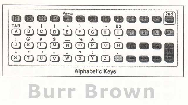
Alphabetic Keys

The alpha portion of the keyboard allows entry of alphabetic characters and special symbols. Characters printed directly on the keycap are entered by pressing the key. Characters printed above the key (shifted functions) are entered by first pressing the 2nd key, then the desired key.

For example, 2nd D would enter the "(" character.

Alphabetic keys are normally entered as upper case. Pressing the A<-»a key (2nd followed by CTRL on the standard keyboard) will switch the keyboard to lower case mode. Pressing this key sequence again will return to upper case mode. (Lower case mode causes the terminal to add 32 to the character code of any character between 065 ("A") and 090 ("Z") thereby generating the corresponding lower case character. Keys with codes outside this range are not affected by the case setting.)


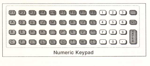
Numeric Keys

The numeric keypad is separate from the alphabetic keys for ease of entering numbers. The arrangement of these keys on the standard keyboard is similar to that used on a telephone.


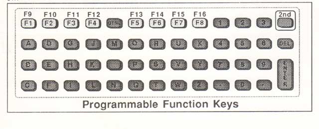
Programmable Function Keys

Eight programmable function keys are located in a row under the display. Each of these keys may be programmed by the host to enter a message up to 40 characters in length. Functions F1 through F8 are entered by pressing the appropriate key. F9 through F16 are entered by first pressing the 2nd key.

Internally, the TM8400 stores two sets of 16 function messages, referred to as the lower and upper function banks. The host computer may choose which bank of function messages is accessed from the keyboard by using the k command.

If the upper bank is selected, the key functions F1 through F16 will enter function messages F17 through F32 respectively. Function messages are stored in non-volatile memory and retained when power is off.


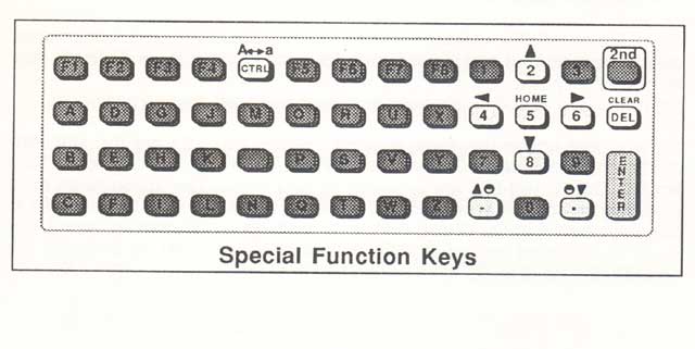
Special Function Keys

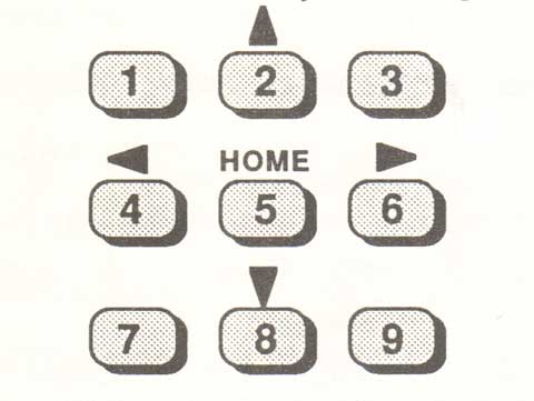
Several keys have special functions. The four directional arrows and the HOME function located above the numeric keys allow the operator to move the display window.
The 2nd key selects the shifted function of the key pressed immediately following it.

The CTRL key algorithmically modifies the keycode transmitted by the key following it, producing the corresponding ASCII control character. (This affects only characters with codes between 064 and 095. Control character codes are generated by subtracting 64 from the normal code.) For example, CTRL followed by G will produce the <BEL> character.
Both the 2nd and CTRL keys cause the cursor to change font, indicating that the next key pressed will be modified.

The A<->a key switches the keyboard between upper and lower case mode for alphabetic characters.

The above special function keys are local and do not transmit characters themselves.

The DEL and CLEAR functions are local in block mode only but transmit <DEL> and <FF> respectively when in character mode. The operation of these keys is described in chapters 10 and 11.


Keyboard Redefinition

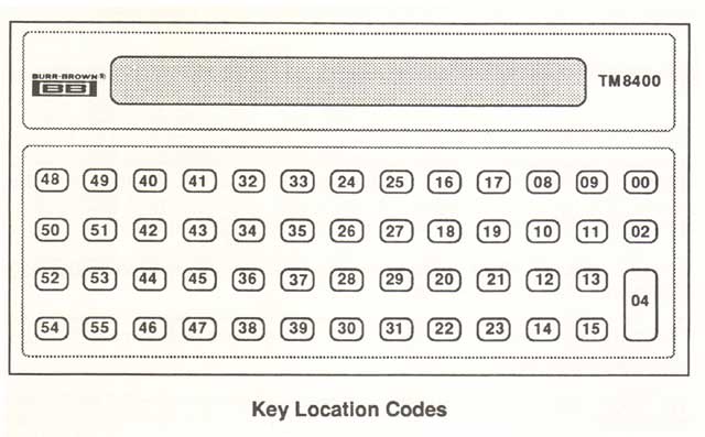
The TM8400's keyboard consists of 51 keys.  Each of these key locations has a unique number between 00 and 55.


The keyboard layout may be redefined by the user to suit a particular application. It is also possible to modify the terminal's character set by assigning characters other than the default ones to keys.

Keyboard redefinition is done by using the host I (lower case "L") command, specifying a normal and shifted code for each location to be defined. Any individual key may be changed without affecting the others. The key definitions are stored in non-volatile memory and retained on power off.

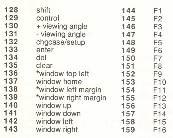
A set of key codes has been defined. Codes 001-127 are the standard ASCII character set. Codes 128-159 designate keys requiring special action. Codes 160-255 are reserved for future use.
The action taken for a particular key code never changes; however, a key code can be assigned to any physical location.

For example, if the letter D is desired, some key must be assigned the code (068). Likewise, a key must be assigned the code (128) if keys are to have shifted functions.

The following table lists the special action codes which may be assigned to keys. Invalid special action codes will be ignored. Assigning a key the code (000) will disable that key.


* Not included in default keyboard layout. These functions may be added to the keyboard if desired, window top left causes the display window to move to the top left corner of the virtual display (the classical home position on a CRT terminal). Window left margin and window right margin are useful when the virtual display width is set to 80.

Removal of Keycaps

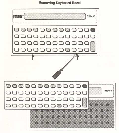
The bezel containing the plastic keycaps may be removed for cleaning or physical rearrangement of keys. Insert a small screwdriver in the two indentations at the bottom of the bezel and gently pry upward. When replacing the key bezel, always insert the top edge first and then snap the bottom into place.


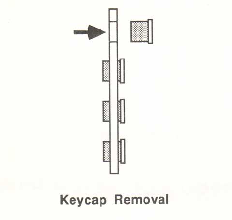
Individual key caps may be snapped out of place by pressing from the front once the bezel is removed.


#15
This is the "display information" from the manual:

Burr Brown TM8400 Display

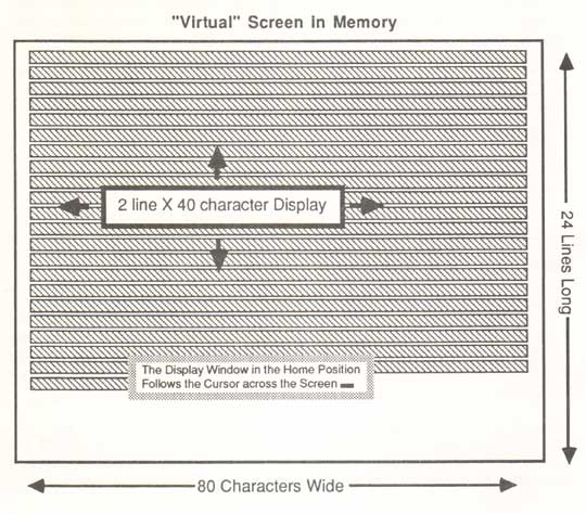
The TM8400's LC display can be thought of as a window into a virtual screen of 1920 characters. The display is buffered in a circular fashion so that as the screen becomes full, new data entered at the bottom of the screen causes the screen to scroll upward.

The point at which characters are entered into the display is indicated by a flashing cursor, which may or may not be visible in the window. Characters written to the display can be made to flash under software control.

The virtual screen may be 48 lines of 40 characters or 24 lines of 80 characters, depending on the display width setting . If the width is set to 80, the display window will move both horizontally and vertically.

When auto wrap is enabled, characters which exceed the screen width will continue on the next line; otherwise, excess characters will be lost.

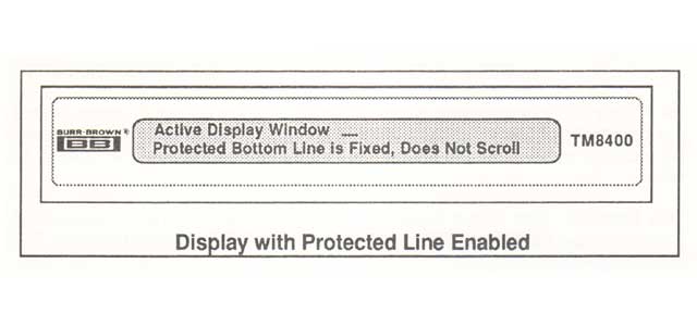
The size of the visible window may be one line of 40 characters or two lines by 40 characters, depending on the display mode selected. When the single line window is used, the top line is a normal display line, and the bottom line is a protected line.

The protected line is always 40 characters in length. This line is fixed and does not scroll. Messages are written to the protected line by the host using the w command.

Since this line has no cursor, cursor control characters between the escape sequence and the command terminator are ignored. Characters written to the protected line will flash when flashing is enabled.


Several other parameters affect the way data is displayed. The display of output messages may be disabled for security and password applications by setting the Output Display parameter to Off.

In character mode operation, the Local Echo setting determines whether data entered into the terminal is displayed when it is transmitted to the host. If Local Echo is set to Off, the host must echo characters to the terminal for display.

Cursor Control

Characters are always entered into the display at the current cursor position. If a character is present at this location, it will be replaced by the new character.

When autowrap is disabled, the cursor will not move past the last character in the current line. This means that extra characters will replace the last display character if the number of characters between <CR>s exceeds the line length.

Several ASCII control characters are provided to control the position of the display cursor:


  • <CR> (013)- move to the beginning of the current line

  • <LF> (010)- move down to the next line in the current column

  • <TAB> (009)- move forward one location in the virtual screen

  • <BS> (008)- move back one location in the virtual screen

  • <VT> (011)- move up to the previous line in the current column

  • <FF> (012)- Clear the display buffer and move the cursor and the window to the beginning of the buffer, (the protected line is not affected)

  • <DEL> (127)- Delete the character before the cursor


When any of the above characters would cause the cursor to move before the beginning of the virtual screen, it is ignored. The cursor may, however, be made to move past the end of the virtual screen, causing the display to scroll.

The Newline and Input Display parameters affect the movement of the cursor and placement of data on the screen.

When Newline is set to On, individual <CR> and <LF> control characters are converted to <CRLF> sequences, moving the cursor to the first position of the next line.

Setting Input Display to One Message per Line causes the terminal to add a <CRLF> sequence to the beginning of each new message received in block mode, resulting in one message per line.

The selection of the Line Terminator in block mode operation can affect whether or not <CR> and <LF> characters sent from the host computer will ever reach the display.

If the terminator is set to <CR>, any <CR> received will be interpreted as an end of message and stripped off.

Likewise, if set to <CRLF>, any <CRLF> sequence received will be stripped off before reaching the display, however, individual <CR>'s not followed by a <LF> or <LF>'s not preceded by a <CR> will reach the display.

Setting the line terminator to <ETX> is suggested when possible to avoid this problem.

Cursor Fonts

The cursor appears as one of four display fonts, depending on the current status of the keyboard.

The standard cursor is an underscore: (_)

When the 2nd key has been pressed, a shift cursor is displayed (s )

Pressing the CTRL key also changes the cursor (c )

Pressing CTRL followed by 2nd produces a fourth cursor font (cs )

The purpose of these cursor changes is to indicate that the next key pressed will be modified by the 2nd or CTRL functions.

Movement of Display Window

The cursor and display window can be moved independently of each other. The display window can be in one of two states. When the window is home, the window always contains the cursor and follows it if it moves beyond the limits of the visible display.

When a two line window is used, the cursor stays on the bottom line of the window, except when the window is at the top of the virtual display and the cursor is in the first line (of the virtual screen).

Several keys allow the operator to manually move the display window away from its home position to view other sections of the virtual screen. These keys are located above the numeric keys on the right side of the keyboard.


An attempt by the operator to move the window in any direction beyond the boundaries of the virtual screen will result in an error beep.

When the window has been moved away from home, it may or may not contain the cursor but does not follow it.

If the display window is moved away from home and left in place, the window will track the text being viewed until it scrolls off the top of the virtual screen. New messages from the host will not be visible in the display if the window has been moved away from the cursor position.

There are two ways for the operator to return the window to the home position so that if will again follow the cursor.

Entering a new message on the keyboard or peripheral will automatically return the window to home, or, the operator may press the HOME key .

Moving the window back with the arrow keys until the cursor is seen will not home the window. To home the window from the host computer, a <FF> may be sent to clear the screen.

The I command may be used to home the window without clearing the screen. This is done by simulating a keyboard entry as described in the example in chapter 4.

In interactive applications using character mode, it may be desirable to redefine the window movement keys so that they instead transmit the characters <VT>,<LF>,<BS>,and <TAB>.

This allows the host to keep track of the position of the window by moving it only with echoed cursor controls. The window would then never leave home.

"Virtual" Screen in Memory


Output Pending Status Indicator

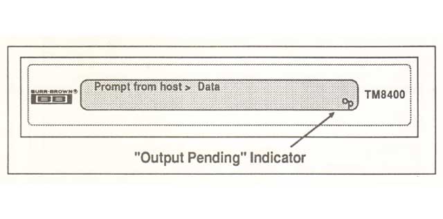
In multidropped operation, an Output Pending condition can exist when the operator has entered data which has not yet been requested by the host.

This condition is indicated by a flashing "Op" in the lower right corner of the display. If this position is occupied by a character the "Op" symbol will alternate with that character so that both can be seen.


Display Backlight Control

For ease of viewing in low light, the display has an electroluminescent backlight. This backlight may be switched on and off under software control.

In order to extend the life of the light source, the backlight features a special Auto On/Off mode which will turn the light off after 10 minutes of inactivity (no input into the terminal).

The display will come on again automatically with any keyboard, peripheral, or auxiliary input. The host may also retrigger the backlight using the f command.

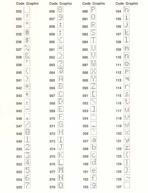
Display Character Set

The following table contains the set of characters which the TM8400 will display. All of the standard printable ASCII characters with codes between 032 and 126 (decimal) may be displayed.


#16
E02 Error / E02 Fault / E02 Alarm

Means: Overcurrent during "deceleration"

Possible Causes: Inverter output was short-circuited, or the motor shaft is locked, or the load is too heavy, or a dual-voltage motor is wired incorrectly.

Note: The Hitachi SJ200 will over current trip at nominally 200% of rated current.

Also, Hitachi SJ200 inverters will trip on over-current to protect the inverter. The motor output turns OFF, hence the motor free-wheels to a stop. Just press the Stop/Reset key to reset the inverter and clear the error.


#17
E03 Error / E03 Fault / E03 Alarm

Means: Overcurrent during "acceleration"

Possible Causes: Inverter output was short-circuited, or the motor shaft is locked, or the load is too heavy, or a dual-voltage motor is wired incorrectly.

Note: The Hitachi SJ200 will over current trip at nominally 200% of rated current.

Also, Hitachi SJ200 inverters will trip on over-current to protect the inverter. The motor output turns OFF, hence the motor free-wheels to a stop. Just press the Stop/Reset key to reset the inverter and clear the error.


#18
E01 Error / E01 Fault / E01 Alarm

Means: Overcurrent while at "Constant" speed

Possible Causes: Inverter output was short-circuited, or the motor shaft is locked, or the load is too heavy, or a dual-voltage motor is wired incorrectly.

Note: The Hitachi SJ200 will over current trip at nominally 200% of rated current.

Also, Hitachi SJ200 inverters will trip on over-current, over-voltage, and under-voltage to protect the inverter. The motor output turns OFF, hence the motor free-wheels to a stop. Just press the Stop/Reset key to reset the inverter and clear the error.


#19
E05 Error / E05 Fault / E05 Alarm

Means: Overload Protection

Possible Cause: Motor overload is detected by the electronic thermal function.


#20
E06 Error / E06 Fault / E06 Alarm

Means: Braking Resistor Overload

Possible Cause: Regenerative braking resistor exceeds usage time or usage ratio.


#21
E07 Error / E07 Fault / E07 Alarm

Means: Overvoltage Protection

Possible Cause: DC bus voltage exceeds a threshold, due to regenerative energy from motor.

Also, Hitachi SJ200 inverters will trip on over-voltage to protect the inverter. The motor output turns OFF, hence the motor free-wheels to a stop. Just press the Stop/Reset key to reset the drive and clear the error.


#22
E08 Error / E08 Fault / E08 Alarm

Means: EEPROM Error / EEPROM Fault

Possible Cause: Built-in EEPROM memory experienced noise, high temperature, etc.


#23
E09 Error / E09 Fault / E09 Alarm

Means: Undervoltage Error (Under-Voltage Fault)

Possible Cause: DC bus voltage decreased enough to cause a control circuit fault.

Also, Hitachi SJ200 inverters will trip on under-voltage to protect the drive. The motor output turns OFF, hence the motor free-wheels to a stop. Just press the Stop/Reset key to reset the inverter and clear the error.


#24
E12 Error / E12 Fault / E12 Alarm

Means: External Trip

Possible Cause: {EXT} input signal detected.

#25
E13 Error / E13 Fault / E13 Alarm

Means: Unattended Start Protection (USP)

Possible Cause: When (USP) was enabled, an error occurred when power was applied while a "Run" signal was present.


#26
E11 Error / E11 Fault / E11 Alarm

Means: CPU Fault / CPU Error

Possible Cause: Built-in CPU had an internal error. (This is basically the same fault as E22)


#27
E22 Error / E22 Fault / E22 Alarm

Means: CPU Fault / CPU Error

Possible Cause: Built-in CPU had an internal error. (This is similar to the E11 alarm.)


#28
E35 Error / E35 Fault / E35 Alarm

Means: Thermistor Fault

Possible Cause: Thermistor input, {THM} and {L}, is over the temperature threshold.


#29
E60 Error / E60 Fault / E60 Alarm

Means: Communications Fault

Possible Cause: The drive/inverter's watchdog timer for the communication network has timed out.

#30
E14 Error / E14 Fault / E14 Alarm

Means: Ground Fault

Possible Cause: A ground fault was detected between the inverter output and the motor. This feature protects the inverter, and does not protect humans.